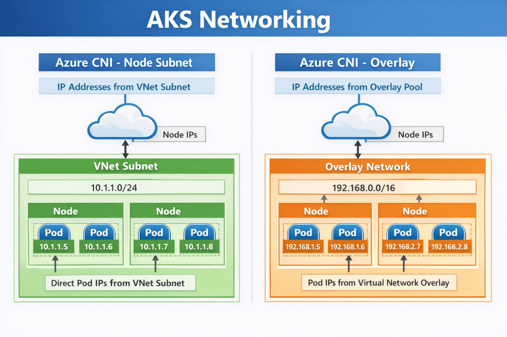

In the previous post on AKS Networking, we explored the different networking models available in AKS and how IP strategy, node pool scaling, and control plane connectivity shape a production-ready cluster. Now we move from how the cluster is networked to how traffic actually flows through it.
If networking defines the roads, this post is about traffic patterns, checkpoints, and border control. Understanding traffic flow is essential for reliability, security, performance, and compliance. In this post we’ll explore:
- north–south vs east–west traffic patterns
- ingress options and when to use each
- internal-only exposure patterns
- outbound (egress) control and compliance design
- how to design predictable and secure traffic flow
Understanding Traffic Patterns in Kubernetes
Before we talk about tools, we need to talk about traffic patterns.
Like the majority of networking you will see in a traditional Hub-and-Spoke architecture, Kubernetes networking is often described using two directional models.
North–South Traffic
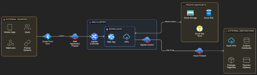
North–south traffic refers to traffic entering or leaving the cluster., so can be ingress (incoming) or egress (outgoing) traffic. Examples include:
Incoming
✔ Users accessing a web app
✔ Mobile apps calling APIs
✔ Partner integrations
✔ External services sending webhooks
Outgoing
✔ Calling SaaS APIs
✔ Accessing external databases
✔ Software updates & dependencies
✔ Payment gateways & third-party services
This traffic crosses trust boundaries and is typically subject to security inspection, routing, and policy enforcement.
East–West Traffic
East–west traffic refers to traffic flowing within the cluster.
Examples include:
- microservices communicating with each other
- internal APIs
- background processing services
- service mesh traffic
This traffic remains inside the cluster boundary but still requires control and segmentation in production environments.
Ingress: Getting Traffic Into the Cluster
Ingress defines how external clients reach services running inside AKS.
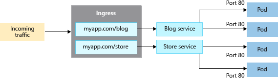
At its simplest, Kubernetes can expose services using a LoadBalancer service type. In production environments, however, ingress controllers provide richer routing, security, and observability capabilities.
Choosing the right ingress approach is one of the most important architectural decisions for external traffic.
Azure Application Gateway + AGIC
Azure Application Gateway with the Application Gateway Ingress Controller (AGIC) provides a native Azure Layer 7 ingress solution.
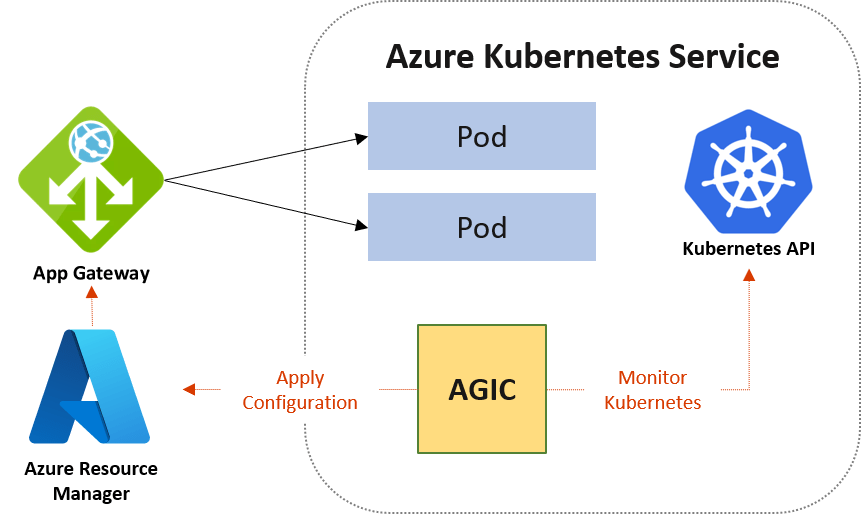
Application Gateway sits outside the cluster and acts as the HTTP/S entry point. AGIC runs inside AKS and dynamically configures routing based on Kubernetes ingress resources.
Why teams choose it
This approach integrates tightly with Azure networking and security capabilities. It enables Web Application Firewall (WAF) protection, TLS termination, path-based routing, and autoscaling.
Because Application Gateway lives in the VNet, it aligns naturally with enterprise security architectures and centralised inspection requirements.
Trade-offs
Application Gateway introduces an additional Azure resource to manage and incurs additional cost. It is also primarily designed for HTTP/S workloads.
For enterprise, security-sensitive, or internet-facing workloads, it is often the preferred choice.
Application Gateway for Containers
Application Gateway for Containers is a newer Azure-native ingress option designed specifically for Kubernetes environments. Its the natural successor to the traditional Application Gateway + AGIC model.
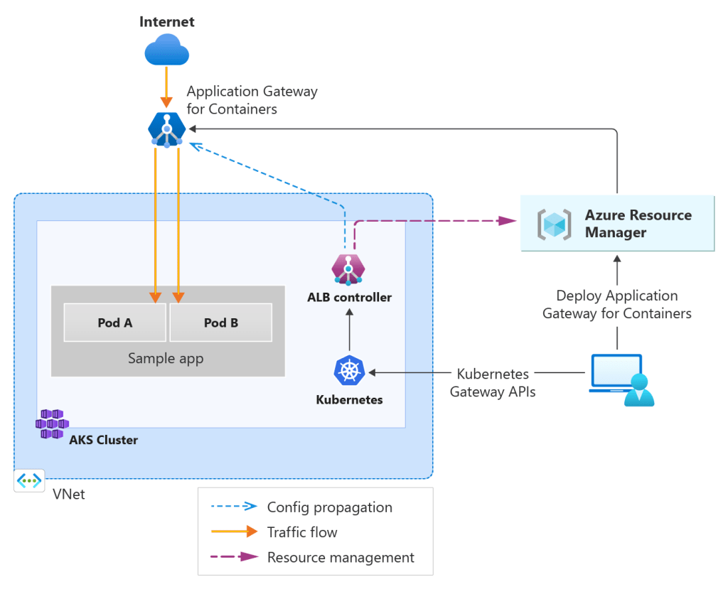
It integrates directly with Azure networking constructs while remaining highly performant and scalable for container-based workloads.
In practical terms, this approach allows Kubernetes resources to directly define how Application Gateway for Containers routes traffic, while Azure manages the underlying infrastructure and scaling behaviour.
Why teams choose it
Application Gateway for Containers is chosen when teams want the security and enterprise integration of Azure Application Gateway but with tighter alignment to Kubernetes-native APIs.
Because it uses the Gateway API instead of traditional ingress resources, it offers a more expressive and modern way to define traffic routing policies. This is particularly attractive for platform teams building shared Kubernetes environments where traffic routing policies need to be consistent and reusable.
Application Gateway for Containers also provides strong integration with Azure networking, private connectivity, and Web Application Firewall capabilities while improving performance compared to earlier ingress-controller models.
Trade-offs
As a newer offering, Application Gateway for Containers may require teams to become familiar with the Kubernetes Gateway API and its resource model.
There is also an additional Azure-managed infrastructure layer involved, which introduces cost considerations similar to the traditional Application Gateway approach.
However, for organisations building modern AKS platforms, Application Gateway for Containers represents a forward-looking ingress architecture that aligns closely with Kubernetes networking standards.
Jack Stromberg has written an extensive post on the functionality of AGC and the migration paths from AGIC and Ingress, check it out here
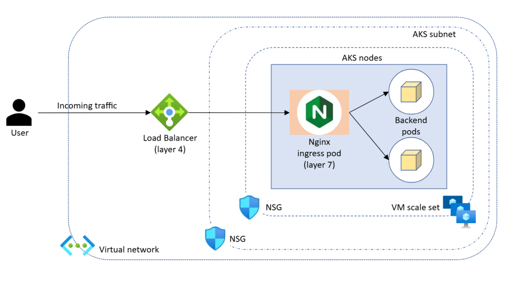
NGINX Ingress Controller
The NGINX Ingress Controller is one of the most widely used ingress solutions in Kubernetes. It runs as pods inside the cluster and provides highly flexible routing, TLS handling, and traffic management capabilities.
And its retiring ….. well, at least the managed version is.
Microsoft is retiring the managed NGINX Ingress with the Application Routing add-on, with support ending in November 2026. The upstream Ingress-NGINX project is being deprecated, so the managed offering is being retired.
However, you still have the option to run your own NGINX Ingress inside the cluster. Requires more management overhead, but …..
Why teams choose it
NGINX provides fine-grained routing control and is cloud-agnostic. Teams with existing Kubernetes experience often prefer its flexibility and maturity.
It supports advanced routing patterns, rate limiting, and traffic shaping, making it suitable for complex application architectures.
Trade-offs
Because NGINX runs inside the cluster, you are responsible for scaling, availability, and lifecycle management. Security features such as WAF capabilities require additional configuration or integrations.
NGINX is ideal when flexibility and portability outweigh tight platform integration.
Istio Ingress Gateway
The final ingress approach to cover is the Istio Ingress Gateway, typically deployed as part of a broader service mesh architecture.
When using Istio on AKS, the ingress gateway acts as the entry point for traffic entering the service mesh. It is built on the Envoy proxy and integrates tightly with Istio’s traffic management, security, and observability features.
Rather than acting purely as a simple edge router, the Istio ingress gateway becomes part of the overall service mesh control model. This means that external traffic entering the cluster can be governed by the same policies that control internal service-to-service communication.
Why teams choose it
Teams typically adopt the Istio ingress gateway when they are already using — or planning to use — a service mesh.
One of the main advantages is advanced traffic management. Istio enables sophisticated routing capabilities such as weighted routing, canary deployments, A/B testing, and header-based routing. These patterns are extremely useful in microservice architectures where controlled rollout strategies are required.
Another major benefit is built-in security capabilities. Istio can enforce mutual TLS (mTLS) between services, allowing ingress traffic to integrate directly into a zero-trust communication model across the cluster.
Istio also provides strong observability through integrated telemetry, tracing, and metrics. Because Envoy proxies sit on the traffic path, detailed insight into request flows becomes available without modifying application code.
For platform teams building large-scale internal platforms, these capabilities allow ingress traffic to participate fully in the platform’s traffic policy, security posture, and monitoring framework.
Trade-offs
Istio comes with additional operational complexity. Running a service mesh introduces additional control plane components and sidecar proxies that consume compute and memory resources.
Clusters using Istio typically require careful node pool sizing and resource planning to ensure the mesh infrastructure itself does not compete with application workloads.
Operationally, teams must also understand additional concepts such as virtual services, destination rules, gateways, and mesh policies.
I’ll dive into more detail on the concept of Service Mesh in a future post.
Internal Ingress Patterns
Many production clusters expose workloads internally using private load balancers and internal ingress controllers.
This pattern is common when:
- services are consumed only within the VNet
- private APIs support internal platforms
- regulatory or security controls restrict public exposure
Internal ingress allows organisations to treat AKS as a private application platform rather than a public web hosting surface.
Designing for Ingress Resilience
Ingress controllers are part of the application data path. If ingress fails, applications become unreachable. Production considerations include:
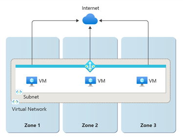
- running multiple replicas
- placing ingress pods across availability zones
- ensuring node pool capacity for scaling
- monitoring latency and saturation
East–West Traffic and Microservice Communication
Within the cluster, services communicate using Kubernetes Services and DNS.
This abstraction allows pods to scale, restart, and move without breaking connectivity. In production environments, unrestricted east–west traffic can create security and operational risk.
Network Policies allow you to restrict communication between workloads, enabling microsegmentation inside the cluster. This is a foundational step toward zero-trust networking principles.
Some organisations also introduce service meshes to provide:
- mutual TLS between services
- traffic observability
- policy enforcement
While not always necessary, these capabilities become valuable in larger or security-sensitive environments.
Egress: Controlling Outbound Traffic
Outbound traffic is often overlooked during early deployments. However, in production environments, controlling egress is critical for security, compliance, and auditability. Workloads frequently need outbound access for:
- external APIs
- package repositories
- identity providers
- logging and monitoring services
NAT Gateway and Predictable Outbound IP
With the imminent retirement of Default Outbound Access fast approaching, Microsoft’s general recommendation is to use Azure NAT Gateway to provide a consistent outbound IP address for cluster traffic.
This is essential when external systems require IP allow-listing. It also improves scalability compared to default outbound methods.
Azure Firewall and Centralised Egress Control
Many enterprise environments route outbound traffic through Azure Firewall or network virtual appliances. This enables:
- traffic inspection
- policy enforcement
- logging and auditing
- domain-based filtering
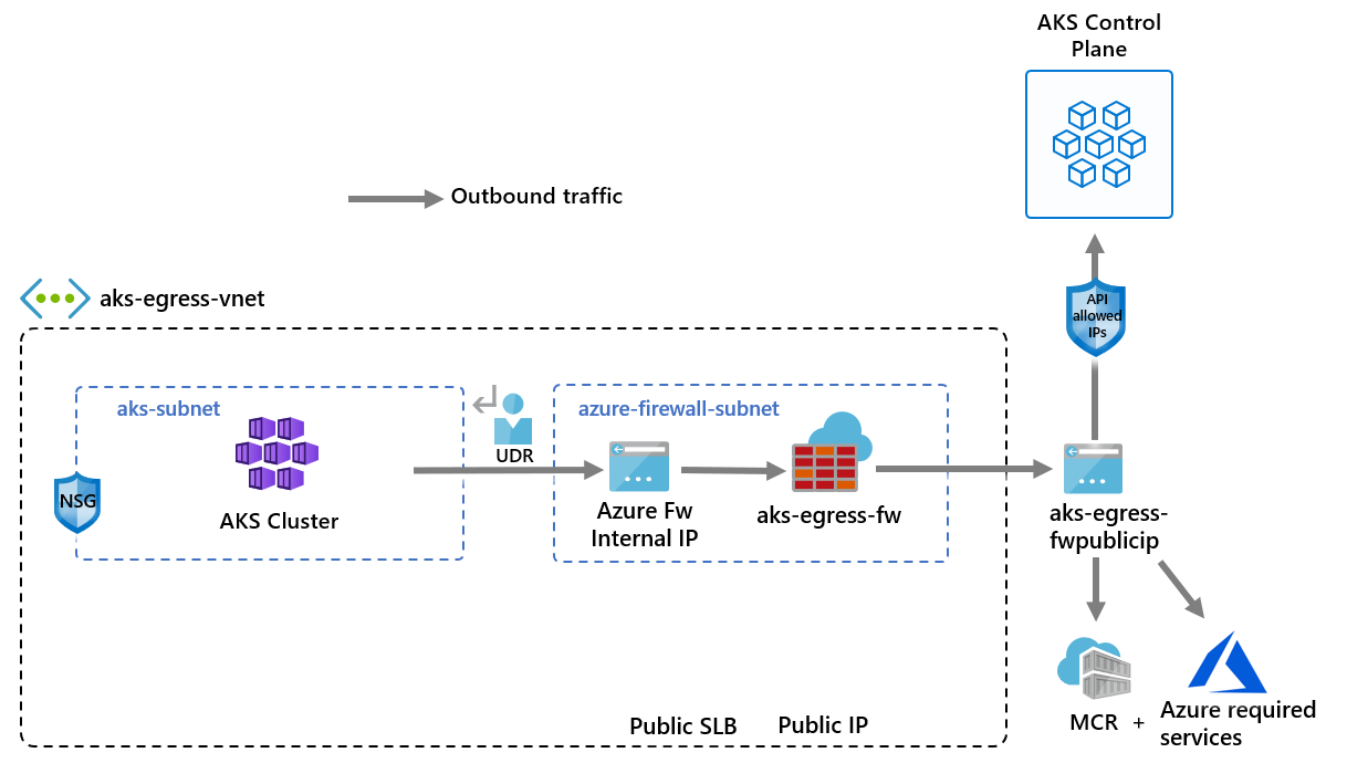
This pattern supports regulatory and compliance requirements while maintaining central control over external connectivity.
Private Endpoints and Service Access
Whenever possible, Azure PaaS services should be accessed via Private Endpoints. This keeps traffic on the Azure backbone network and prevents exposure to the public internet.
Combining private endpoints with controlled egress significantly reduces the attack surface.
Designing Predictable Traffic Flow
Production AKS platforms favour predictability over convenience.
That means:
- clearly defined ingress entry points
- controlled internal service communication
- centralised outbound routing
- minimal public exposure
This design improves observability, simplifies troubleshooting, and strengthens security posture.
Aligning Traffic Design with the Azure Well-Architected Framework
Operational Excellence improves when traffic flows are observable and predictable.
Reliability depends on resilient ingress and controlled outbound connectivity.
Security is strengthened through restricted exposure, network policies, and controlled egress.
Cost Optimisation improves when traffic routing avoids unnecessary hops and oversized ingress capacity.
What Comes Next
At this point in the series, we have designed:
- the AKS architecture
- networking and IP strategy
- control plane connectivity
- ingress, egress, and service traffic flow
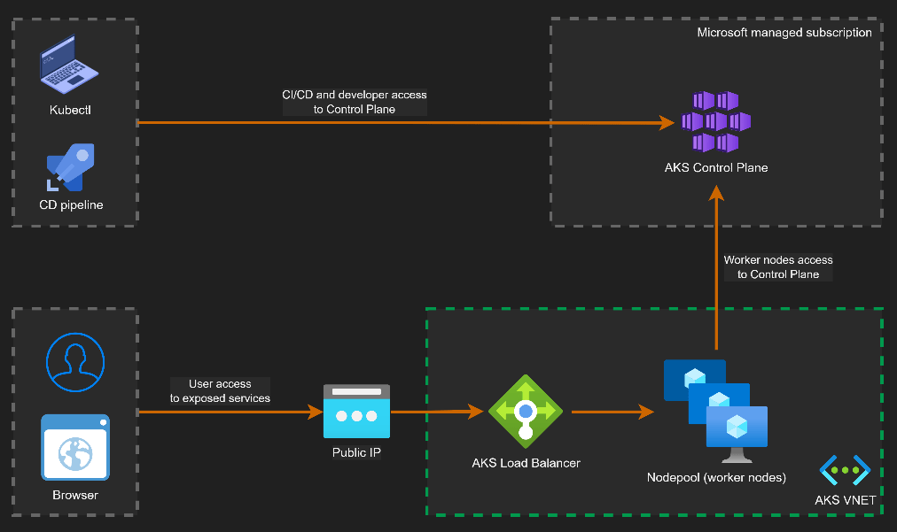
In the next post, we turn to identity and access control. Because
- Networking defines connectivity.
- Traffic design defines flow.
- Identity defines trust.
See you on the next post