


Its Day 11 of 100 Days of Cloud, and as promised its part 2 of Azure Virtual Networks.
In the last post I covered creating a Virtual Network, having multiple subnets and also have NSG Rules govern how subnets within the same Virtual Network communicate.
Today’s post is about Virtual Network Peering, or Vnet Peering. This allows you to seamlessly connect 2 Azure Virtual Networks. Once connected, these networks communicate over the Microsoft backbone infrastructure, so no public internet, gateways or VPN’s are required for the networks to communicate.
Overview of Vnet Peering
Vnet peering enables you to connect two Azure virtual networks without using VPN or Public Internet. Once peered, the virtual networks appear as one, for connectivity purposes. There are two types of VNet peering.
- Regional VNet peering connects Azure virtual networks in the same region.
- Global VNet peering connects Azure virtual networks in different regions. When creating a global peering, the peered virtual networks can exist in any Azure public cloud region or China cloud regions, but not in Government cloud regions. You can only peer virtual networks in the same region in Azure Government cloud regions.
Once the peering connection is created, traffic routed through Microsoft’s private backbone network only, it never goes out onto the internet.
Naturally, Global Vnet Peering has a higher cost than Regional Vnet peering. Check out Microsoft’s Azure Pricing site for Virtual Networks here, which gives full details of the costs of each.
Benefits of Vnet Peering
The benefits of using virtual network peering, include:
- Resources in either network can directly connect with resources in the peered network.
- A low-latency, high-bandwidth connection between resources in peered virtual networks.
- Use of NSG’s in peered Vnets to block access to other virtual networks or subnets.
- Data Transfer between virtual networks across subscriptions, Azure Active Directory tenants, deployment models, and Azure regions.
- Peering of Networks created using ARM Templates or using classic deployment models (Portal/PowerShell/CLI) to each other.
- No downtime in either virtual network is required when creating the peering, or after the peering is created.
Demo
Let’s dive into a demonstration to see how this works. To do this, I’ll need to create 2 VMs in separate Virtual Networks. I’ll create these in separate regions also. Another thing I need to make sure of is that the Subnets do not overlap.
So I’ll jump into PowerShell first and use this command to create a Resource Group called “Prod_VMs”:
New-AzVM -ResourceGroupName “Prod_VMs” -Location northeurope -Name “ProdVM1” -VirtualNetworkName “ProdVM1” -SubnetName “ProdVM1” -SubnetAddressPrefix “192.168.2.0/24” -SecurityGroupName “ProdVM1” -OpenPorts 3389 -ImageName Win2016Datacenter -Size Standard_B2s -OsDiskDeleteOption Delete -Credential (Get-Credential) -Verbose
I’ll then use the same command with different input values to create the second VM in a resource group called “Test_VMs”:
New-AzVM -ResourceGroupName “Test_VMs” -Location eastus -Name “TestVM1” -VirtualNetworkName “TestVM1” -AddressPrefix “10.10.0.0/16” -SubnetName “TestVM1” -SubnetAddressPrefix “10.10.2.0/24” -SecurityGroupName “TestVM1” -OpenPorts 3389 -ImageName Win2016Datacenter -Size Standard_B2s -OsDiskDeleteOption Delete -Credential (Get-Credential) –Verbose
Once the 2 VMs are created, we need to note the Private IP Addresses they’ve been assigned. In the “Overview” screen on each, we note that they have been given the first available IP in their Subnets.
So it’s 192.168.2.4 for ProdVM1:

And its 10.10.2.4 for TestVM1:

And just to be sure, lets launch TestVM1 and see if we can ping ProdVM1:

Back in the Portal, I’ll go into the TestVM1 Virtual Network and in the left hand menu go to Peerings:
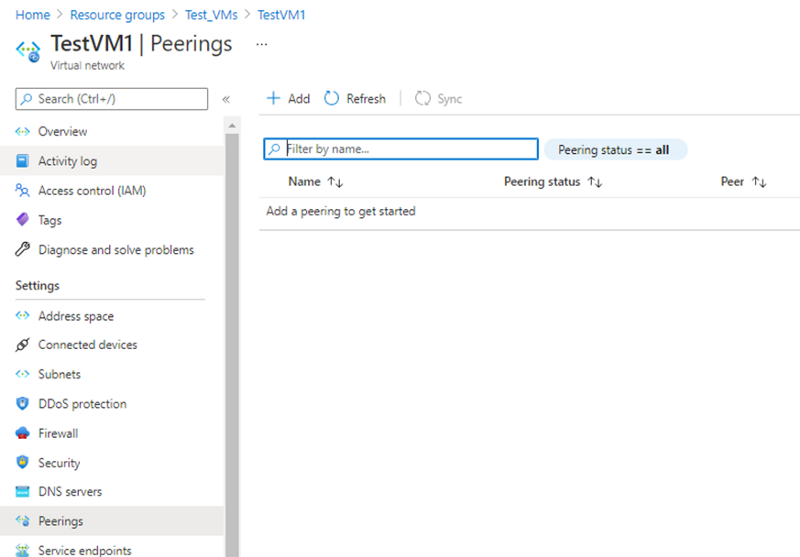
And when I click Add, this brings me into the options for adding Peering:

As I can see, I need to specify the Peering in both Directions. I can also see that I can specify to Allow or Block Traffic, so I can peer the networks but only allow traffic to flow in one direction.
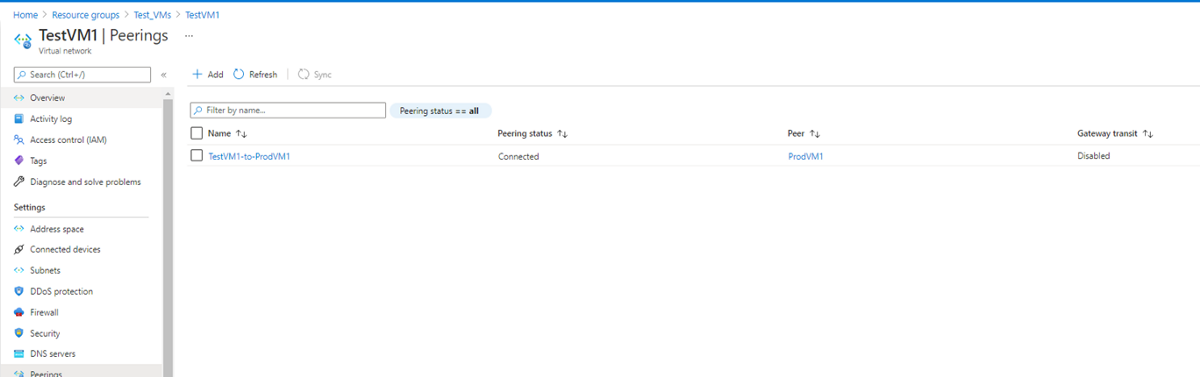
So when I click “Add”, this sets up the Peering on both sides:

I can now see on “TestVM1” that I’m connected to “ProdVM1”:
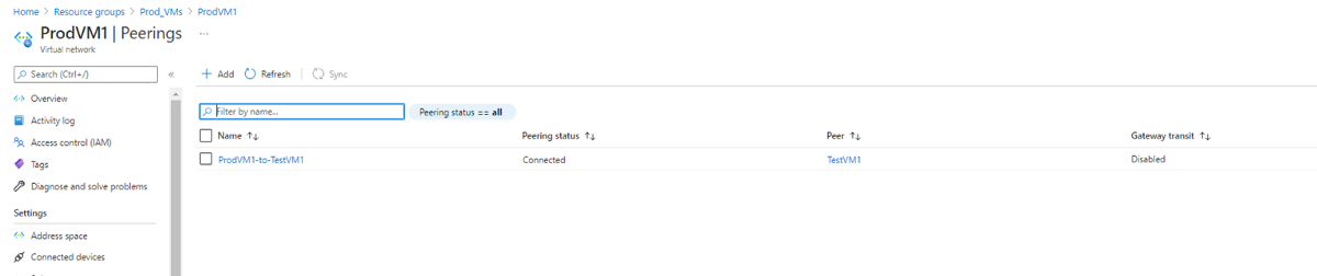
And same on the other side:
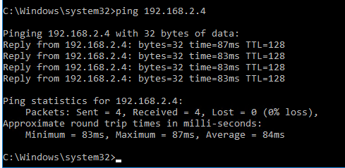
Now, lets test ping connectivity from TestVM1 to ProdVM1:
And that is how to set up Vnet Peering of Azure Virtual Networks!
Important Points!
There a few things you need to know about Vnet Peering before we close this post out. Vnet Peerings are not transitive. So in a Hub and Spoke Topology where VnetA is peered with VnetB, and VNetA is peered with VnetC, this doesn’t automatically mean that VNetB can talk to VnetC. There are 3 options available to make this work:
- VnetB would need to be peered directly with VnetC. However, lets say you have a large environment and would need to create multiple peerings. This would then create a Mesh Topology which is more difficult to manage in the long term.
- The second option is to use Azure Firewall or another virtual network appliance in the Hub Network. Then create routes to forward traffic from the Spoke Networks to the Azure Firewall, which can then route to the other Spoke Networks. We saw in the “Add peering” screen the option to Allow “Traffic Forwarded from a remote Virtual Network”, this needs to be enabled.
- The third option is to use VPN gateway transit on the Hub Virtual Network to route traffic between spokes. This is effectively the same option as Azure Firewall, but this choice will impact latency and throughput
Both option 2 and 3 can also be used to route traffic from on-premise networks when using Site-to-Site (S2S) or Point-to-Site (P2S) connections to Azure.
Conclusion
I hope you enjoyed this post on Azure Virtual Networks! Next time, I’ll create a P2S VPN Connection in order to connect directly to my Virtual Networks from my laptop via a Gateway Subnet.
Hope you enjoyed this post, until next time!!

2 thoughts on “100 Days of Cloud — Day 11: Azure Virtual Networks (Part 2 — Peering)”