I’ve been working with a customer who wants to migrate from Azure SQL Server to Azure SQL Managed Instance. It was the right choice for them – they want to manage multiple databases, so moving away from the DTU Model combined with the costs of running each database indepenently made this a simple choice.
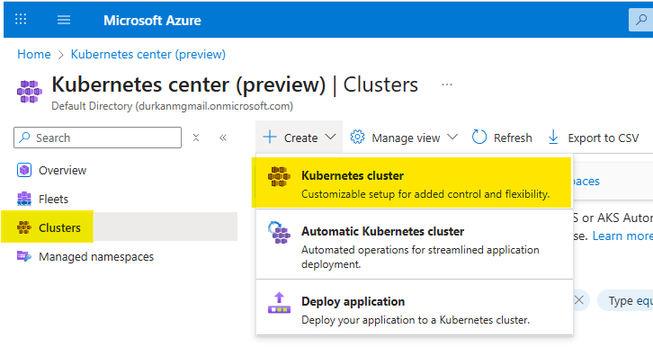
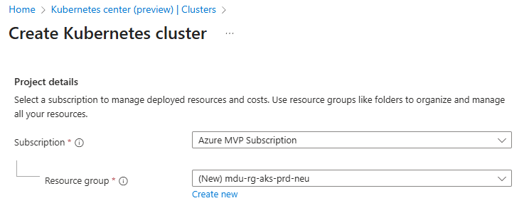
So, lets go set up the deployment. We’ll just deploy it into the same subnet, as it will make life easier during the migration phase……
And it failed. So like most teams would, everyone went looking in the usual places:
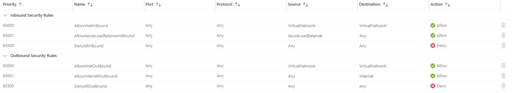
- Was it the NSG?
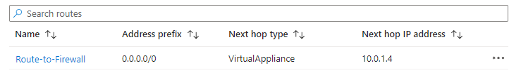
- Was it the route table?
- Was there an address space overlap somewhere?
- Had DNS been configured incorrectly?
- Was there some hidden policy assignment blocking the deployment?
The problem was three words in the Azure documentation that nobody on the team had flagged: requires subnet delegation.
And that was it. A deployment failure caused by something that takes about ninety seconds to fix when you know what you’re looking for.
The frustrating part is not that subnet delegation exists. In fairness, Azure has good reasons for it. The frustrating part is that it often surfaces as a deployment failure that sends you in entirely the wrong direction first.
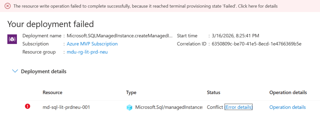
Terminal Provisioning State. The Azure error for everything that tells you nothing…….
This post is about what subnet delegation actually is, why it breaks deployments in ways that are surprisingly difficult to diagnose, and — more importantly — how to make sure it never catches you out again.
What is Subnet Delegation?
At the simplest level, subnet delegation is Azure’s way of saying:
this subnet belongs to this service now.
Not in the sense that you lose visibility of it. Not in the sense that you cannot still apply controls around it. But in the sense that a particular Azure service needs permission to configure aspects of that subnet in order to function properly.
The reason for this is straightforward. Some services need to apply their own network policies, routing rules, and management plane configurations to the subnet. They can’t do that reliably if other resources are competing for the same address space. So Azure introduces the concept of delegation: the subnet is formally assigned to a specific service, and that service becomes the owner.
A delegated subnet belongs to one service. That’s it. No virtual machines, no load balancers, no other PaaS services sharing the space alongside it. The subnet is reserved for the delegated service, not just partially occupied by it.
What Happens When You Get It Wrong
The moment you try to place another resource into a delegated subnet — or deploy a service that requires delegation into a subnet that hasn’t been configured for it — the deployment fails.
And Azure’s error messaging in these situations is not always helpful.
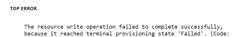
What you typically get is a generic deployment failure (I mean, what the hell does “terminal provisioning state” mean anyway???). The portal or CLI may or may not surface an error that points you at the resource configuration, and the natural instinct is to start checking the things you know: NSG rules, route tables, address space availability. These are the usual suspects in VNet troubleshooting. You work through them methodically and find nothing wrong — because nothing is wrong with them.
What you don’t immediately think to check is the delegation tab on the subnet properties. Why would you? In most VNet troubleshooting scenarios, subnet delegation never comes up. For architects who spend most of their time working with IaaS workloads, it’s simply not part of the mental checklist.
Which Services Require It?
Subnet delegation isn’t a niche requirement for obscure services. It applies to some of the most commonly deployed PaaS workloads in enterprise Azure environments.
At this point, its important to distinguish between “Dedicated” and “Delegated” subnets. Some Azure services such as Bastion, Firewall and VNET Gateway have specific naming and sizing requirements for the subnets that they live in, which means they are dedicated.
I’ve tried to summarize in the table below the services that need both dedicated and delegated subnets. The list may or may not be exhaustive – the reason is that I can’t find a single source of reference on Microsoft Learn or GitHub that shows me what services require delegation. So buddy Copilot may have helped with compiling this list …..
| Azure service | Requirement | Notes |
|---|---|---|
| Compute & containers | ||
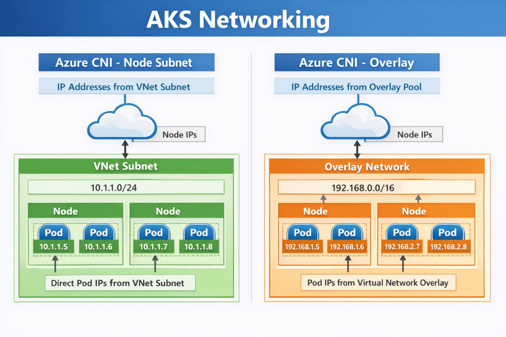
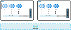
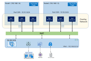
| Azure Kubernetes Service (AKS) — kubenet | Dedicated | Node and pod CIDRs consume the entire subnet; mixing breaks routing |
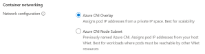
| AKS — Azure CNI | Dedicated | Each pod gets a VNet IP; subnet exhaustion risk with shared use |
| Azure Container Instances (ACI) | Delegation | Delegate to Microsoft.ContainerInstance/containerGroups |
| Azure App Service / Function App (VNet Integration) | Delegation | Delegate to Microsoft.Web/serverFarms; /26 or larger recommended |
| Azure Batch (simplified node communication) | Delegation | Delegate to Microsoft.Batch/batchAccounts |
| Networking & gateways | ||
| Azure VPN Gateway | Dedicated | Subnet must be named GatewaySubnet |
| Azure ExpressRoute Gateway | Dedicated | Also uses GatewaySubnet; can co-exist with VPN Gateway in same subnet |
| Azure Application Gateway v1/v2 | Dedicated | Subnet must contain only Application Gateway instances |
| Azure Firewall | Dedicated | Subnet must be named AzureFirewallSubnet; /26 minimum |
| Azure Firewall Management | Dedicated | Requires separate AzureFirewallManagementSubnet; /26 minimum |
| Azure Bastion | Dedicated | Subnet must be named AzureBastionSubnet; /26 minimum |
| Azure Route Server | Dedicated | Subnet must be named RouteServerSubnet; /27 minimum |
| Azure NAT Gateway | Delegation | Associated via subnet property, not a formal delegation; can share subnet |
| Azure API Management (internal/external VNet mode) | Dedicated | Recommended dedicated; NSG and UDR requirements make sharing impractical |
| Databases & analytics | ||
| Azure SQL Managed Instance | Both | Dedicated subnet + delegate to Microsoft.Sql/managedInstances; /27 minimum |
| Azure Database for MySQL Flexible Server | Both | Dedicated subnet + delegate to Microsoft.DBforMySQL/flexibleServers |
| Azure Database for PostgreSQL Flexible Server | Both | Dedicated subnet + delegate to Microsoft.DBforPostgreSQL/flexibleServers |
| Azure Cosmos DB (managed private endpoint) | Delegation | Delegate to Microsoft.AzureCosmosDB/clusters for dedicated gateway |
| Azure HDInsight | Dedicated | Complex NSG rules make sharing unsafe; dedicated strongly recommended |
| Azure Databricks (VNet injection) | Both | Two dedicated subnets (public + private); delegate both to Microsoft.Databricks/workspaces |
| Azure Synapse Analytics (managed VNet) | Delegation | Delegate to Microsoft.Synapse/workspaces |
| Integration & security | ||
| Azure Logic Apps (Standard, VNet Integration) | Delegation | Delegate to Microsoft.Web/serverFarms; same as App Service |
| Azure API Management (Premium, VNet injected) | Dedicated | One subnet per deployment region; /29 or larger |
| Azure NetApp Files | Both | Dedicated subnet + delegate to Microsoft.Netapp/volumes; /28 minimum |
| Azure Machine Learning compute clusters | Dedicated | Dedicated subnet recommended to isolate training workloads |
| Azure Spring Apps | Both | Two dedicated subnets (service runtime + apps); delegate to Microsoft.AppPlatform/Spring |
If you’re building Landing Zones for enterprise workloads, you will encounter a significant number of these. Quite possibly in the same deployment cycle.
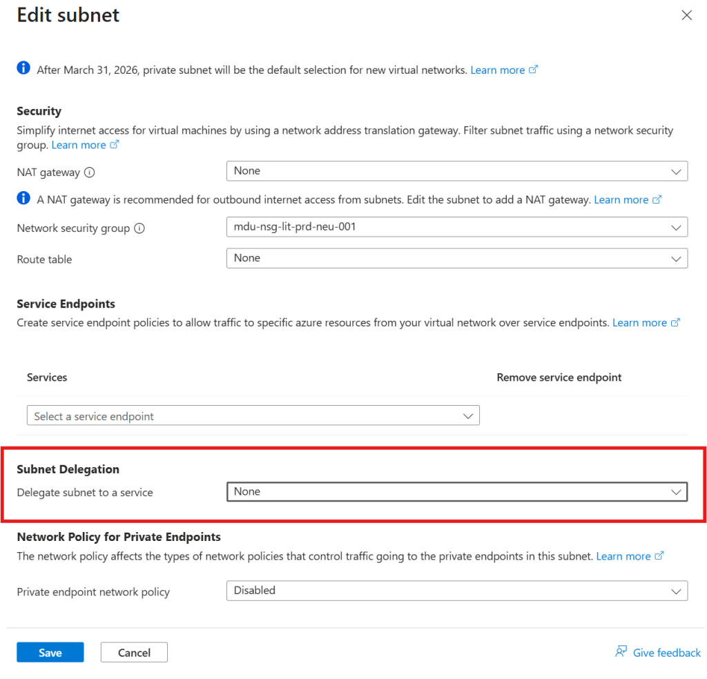
It’s also worth noting that Microsoft surfaces the delegation identifier strings (like Microsoft.Sql/managedInstances) in the portal when you configure a subnet — but only once you know to look there. These identifiers are also what you’ll specify in your IaC templates, so knowing the right string for each service before you deploy is part of the preparation work.
Why This Catches Architects Out
There’s a pattern worth naming here, because it’s the reason this catches people who really should know better — including architects who’ve been working in Azure for years.
When you build a Solution on Azure or any other cloud platform, you make a lot of network design decisions up front: address space, subnets, NSGs, route tables, peerings, DNS. These decisions form a mental model of the network, and that model tends to stay fairly stable once the design is locked.
Subnet delegation is easy to miss in that process because it isn’t a networking concept in the traditional sense. You’re not configuring routing, access control, or address space. You’re assigning ownership of a subnet to a service. That’s a different kind of decision, and it lives in a different part of the portal to everything else you’re configuring.
During a deployment, when the pressure is on and the clock is running, nobody goes back to check the delegation tab unless they already know delegation is the issue. And you only know delegation is the issue once you’ve already ruled out everything else.
What the Fix Actually Looks Like
Once you know what you’re looking for, the resolution is straightforward.
In the Azure Portal, navigate to the subnet, open the delegation settings, and assign the appropriate service. The delegation options available correspond to the services that support or require it — you select the right one, save, and retry the deployment.
That’s it. That’s the ninety-second fix.
In Terraform, it looks like this:
delegation { name = "sql-managed-instance-delegation" service_delegation { name = "Microsoft.Sql/managedInstances" actions = [ "Microsoft.Network/virtualNetworks/subnets/join/action", "Microsoft.Network/virtualNetworks/subnets/prepareNetworkPolicies/action", "Microsoft.Network/virtualNetworks/subnets/unprepareNetworkPolicies/action" ] }}
If you’re deploying via infrastructure-as-code — which you should be for any Landing Zone work — delegation needs to be defined in the subnet configuration from the start, not added reactively when a deployment fails.
Conclusion
Subnet delegation is a small concept with an outsized potential to cause problems during deployments and migrations. The key points:
- Some PaaS services require exclusive control over a dedicated, delegated subnet
- Deployment failures caused by missing delegation are poorly surfaced by Azure’s error messaging, which means diagnosis takes much longer than the fix
- The services that require delegation include SQL Managed Instance, Container Instances, Databricks, Container Apps, and NetApp Files — these are common enterprise workloads, not edge cases
- The fix, once identified, takes about ninety seconds
- The right response is to make delegation a first-class design consideration in your subnet inventory and Landing Zone documentation
And if you haven’t hit this yet: now you’ll know what you’re looking at before the next deployment.